
 |
| Photo by Robina Weermeijer |
In this article, we are not going to mention how the ventilator's preventive maintenance is done as we already covered that in a different article. But we will be shedding light on the various modes of operation in addition to explaining the various parts of a ventilator in a simplified way.
Ventilators or respirators are devices used to assist patients in ventilating their lungs and they are divided into two categories:
- Controller ventilator
- Assisted ventilator
For controlled ventilation,
the respiratory ventilation of the patient is determined by the machine, and it
sets the ventilator cycle. If the patient tried to ventilate, this will affect
the machine, and it can oppose it too.
As for the "assister" mode ventilator,
the respiratory ventilation is determined or controlled by the patient himself. So
it assists rather than controls the patient in ventilation.
Another classification of
ventilation is:
-
Negative
pressure ventilation.
-
Positive
pressure ventilation.
For positive pressure ventilators, pressure, varying between atmospheric pressure and positive pressure, is applied and the air is blown into the lungs. Thus an exchange of gases is done in the patient's lungs.
Machine Components
- Breathing circuit (inspiration – expiration)
- A controlling system that defines the characteristics of the cycle used
- A gas supply
- Monitor
- Valves, pressure sensors, and alarm systems.
Mode/breath
type availability on 760 Ventilators:
- VCV (volume control ventilation) breathe type.
- PCV (pressure control ventilation) breathe type.
- PSV ( pressure support ventilation) breath type (support pressure setting)
- PSV (rise time factor and exhalation sensitivity setting)
- SIMV (Synchronous Intermittent Mandatory Ventilation) mode
- Apnea ventilation (choice of VCV or PCV breath type)
Functional description
By pressing keys and turning the knob on the ventilator keyboard, the operator gives initial instructions and data to the ventilator. The user interface micro-controller processes this information and stores it in the ventilator’s memory. The breath delivery micro-controller uses this stored information to control and monitor the flow of gas to and from the patient.
The
700 series ventilator uses a flow trigger to recognize patient effort. The
trigger monitors flow from the piston during exhalation. When the patient
inhales, patient circuit pressure drops very slightly below end-expiratory
pressure. At the same time, the piston moves forward to deliver flow to the
ventilator breathing circuit and maintain the preset PEEP/CPAP level. The level
of flow depends on the patient’s effort. If this flow exceeds the user-set
level, the ventilator triggers. By design, the ventilator attempts to maintain
PEEP even with the presence of a circuit leak. Since a leak drives the piston to
deliver more flow to make up for pressure losses. A circuit leak can require an
increase in the flow trigger level to avoid auto cycling.
 |
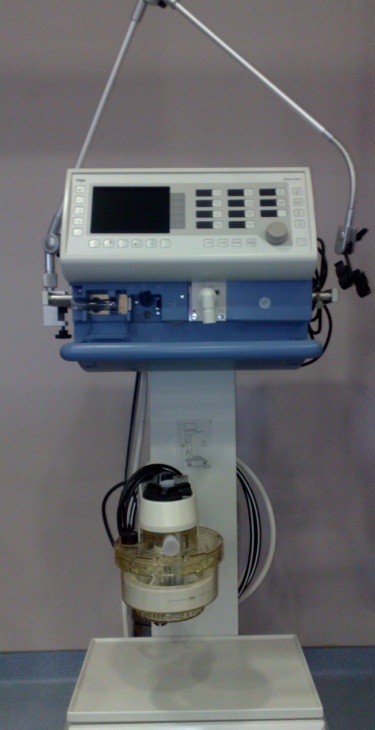
| Puritan-Bennett Ventilator 760 Series |
The oxygen from a cylinder or wall outlet enters the ventilator through a hose and oxygen fitting. The fitting is available in several versions. Once inside the ventilator, the oxygen is regulated to a pressure the ventilator can use and then mixed with air, according to the selected %O2.
The flow-triggered piston/cylinder system and motor controller circuit control the flow of gas to the patient. On the 760 Ventilator in PCV or PSV, the rate of flow is also determined by the preset rise time factor. This system is designed with a minute gap (about the size of a thin sheet of paper) between the piston and the cylinder wall. This design eliminates friction between the piston and cylinder, allowing it to respond more rapidly than a “sealed” system.
The piston delivers the mixed air and oxygen through the inspiratory manifold system, and out to the patient. The oxygen concentration and temperature of the delivered gas are monitored here. This is done using a galvanic oxygen sensor and a thermistor. The galvanic sensor generates a voltage proportional to the partial pressure of oxygen. From which the oxygen concentration is more than ten percentage points above or below the %O2 setting.
The inspiratory manifold system also includes a safety valve to relieve patient pressure if necessary. For example, if the ventilator breathing circuit is kinked or occluded.
The patient includes the components external to the ventilator that route gas between the ventilator and the patient. These components include the inspiratory filter. Which protects against contamination between the ventilator and patient. A humidification device, ventilator breathing circuit, the tubing through which the gas travels, collector vial (which protects the exhalation system from moisture in the exhaled gas, and can be emptied without losing circuit PEEP), and an expiratory filter (which limits the bacteria in the patients' exhaled gas from escaping to room air or contaminating the ventilator).
Keyboard or Keypad
The 740 keyboard is divided into three sections
- VENTILATOR SETTING: Where you set
breath delivery variables.
- PATIENT DATA: Where you set alarm
limits and view the monitored pressures, breath timing, and volumes.
- VENTILATOR STATUS: Where you see
the alarm status and operating condition of the ventilator.
 |
| User Interface Block Diagram (740 Keyboard) |
Ventilator Setup
Ventilator Settings
The ventilator setting section of the keyboard allows you to select the ventilation mode, breath type, and settings. To change the mode and setting, select the mode, then the breath type, and then the ventilator setting. The keys flash during setup and mode changes to ensure that you review all pertinent settings. The keyboard is designed to minimize accidental or unintentional changes.
The table summarizes
the functions of the keys, knobs, and indicators in the ventilator setting
section of the keyboard. Ventilator settings are also limited by these breaths delivery boundaries:
-
I: E ratio ≤ 4:1 for PCV, ≤ 3:1
for all other breath types
-
Inspiratory time = 0.2 to 8
seconds (excluding plateau)
- Expiratory
time ≥0.2 seconds
- PEEP/CPAP + SUPPORT PRSSURE or
INSPIRTORY PRESSURE ≤ 80 cmH2O (80 hpa)
Pneumatic schematic
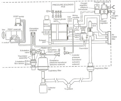 |
| Pneumatic Schematic |
The Pneumatic Schematic diagram shows the pneumatic circuit and how the ventilator controls the flow of air to be supplied to the patient.
Composition
1- 4 lamps that have the following functions:
- AC
power supply indicator lamp.
- Internal
battery indicator lamp.
- Alarm
indicator lamp.
- Synchronous
triggering indicator lamp.
2- LCD
and control
3-pressure
meter: it is dedicated to measuring the pressure of air that is coming out of the machine.
4-Air way: it connects to an inlet port of humidifier with a tube of 22 mm during inhalation phase, compressed gas in ventilator will be supplied to the breathing circuit through this port.
5-Oxygen supply: we can limit the flow as we want using oxygen supply.
6- Humidifier: can heat air and add humidity to the air.
7-Expiration valve: Takes CO2 from the patient to outside.
8-Temperature sensor: Measures air temperature
9-Blue line or airway expiration valve: it connects to pressure sensor to measure out pressure for the patient.
At
the backside of the machine we have:
- 2
cables for the ventilator and humidifier.
-
Timers.
-
2 fusses for protection from AC and one for DC.
Simplified Ventilator Block Diagram
 |
| Ventilator Simplified Block Diagram |
Ventilator Modes and How they Work?
There are 3 main modes that the ventilator can operate on
- A/C Mode
- SPONT Mode
- SIMV Mode
A/C Mode
During this mode, the ventilator will be delivering mandatory breaths ONLY! Using VCV or PCV (Volume Controlled Ventilation or Pressure Control Ventilation).
During VCV mode the ventilator will deliver breaths that are based on the set Tidal Volume and Peak Flow Settings
During PCV mode the ventilator will deliver breaths that are based on the Inspiratory Pressure. I: E ratio (inspiratory: Expiratory Ratio) or inspiratory time and Rise Time Factor
In A/C Mode, the Respiratory Rate setting determines when the VIM (Ventilator-Initiated Mandatory) breath is delivered. However, Patient-Initiated Mandatory PIM breath or Operator-Initiated Mandatory OIM breath can also be performed in this mode. OIM and PIM will increase the respiratory rate and minute volume.
Patient- Initiated Mandatory PIM breath is delivered when the ventilator detects an effort made by the patient, Operator-Initiated Mandatory OIM breath is delivered when the operator usually the nurse presses Manual Insp button,
SPONT Mode
During SPONT mode the ventilator helps the patient inspiratory effort to sustain the set level of support pressure. The patient triggers all spontaneous breaths and influences the inspiratory flow, tidal volume and inspiratory time.
The Rise Time Factor setting determines how fast the target pressure is achieved. Exh Sensitivity setting will determine the point where the breath cycles to exhalation
During SPONT Mode Operator-Initiated Mandatory breath that can be triggered by pressing on the Manual Insp button.
SIMV Mode
A combination of mandatory and spontaneous breaths can be delivered during SIMV mode. Mandatory breaths are triggered by the ventilator, patient or operator while spontaneous breaths are triggered by the patient.
Ventilator Alarm Testing
Testing the ventilator alarms is an important step to make prior to attaching the ventilator to a patient
Types of Alarms that can be tested
- Low Insp Pressure
- Low Exhalation Tidal Volume
- Disconnect
- High Pressure
- Continuous Hi-Pressure
- Loss AC Power
- APNEA
- % O2 low
Settings to Apply before starting
Mode A/C
Respiratory Rate 5/min
Tidal Volume 500 ml
Peak Flow 60L/min
Plateau 0 s
High Rate 100/min
Low Inpiration Pressure 3 cmH2O (3 hPa)
High Pressure 50 cm cmH2O (50 hPa)
High Tidal Volume 1500 ml
Low Tidal Volume 5 ml
low Minute volume 0 L
PEEP/CAP 5 cm cmH2O (5 hPa)
Trigger Sensitivity 3L/min
Connect oxygen source and set the ventilator to operation, also attach an adult or pediatric breathing circuit then attach a test lung* to the wye.
* If you don't have a test lung what can you do? for suggestion please post in the comments below:
Testing Low Inspiration Pressure, Low Ex Tidal Volume, and Disconnect Alarms
First, you need to allow the ventilator to perform at least 10 breaths, during the inspiratory phase of a breath disconnect the test lung.
You should get the Low Insp Pressure alarm during the first breath after you disconnect the test lung. The Disconnect and Lo Ex Tidal Volume Alarms are triggered after the fourth breath.
Testing the High-Pressure alarm
Change the High-Pressure alarm setting to 11 cm cmH2O (11 hPa) then press the reset key to reset the Disconnect alarm. After that block the wye, the ventilator should terminate inspiration without alarming on first breath, then the ventilator announces a High-Pressure alarm during the second alarm.
Testing the Continuous Hi-Pressure alarm
Reset the high-pressure alarm setting to 20 cm cmH2O (20 hPa) then block the exhaust port and press the reset alarm key to reset all alarms.
Now press the Manual Insp, one breath after the ventilator must announce a continuous Hi Pres Alarm. In case the alarm was not triggered make sure that the breathing circuit is mot leaking)
Now return everything to the first settings by unblocking the Exhaust port, unblock the wye and reconnect the test lung. Also, change the alarm setting 50 cm cmH2O (50 hPa). Finally, press the reset alarm key to rest all alarms.
Testing AC Power Alarm Test
Make sure that the battery is fully charged before starting this test.
Allow the ventilator to deliver 3 or more breaths, now disconnect the power cord from AC power. Then the ventilator will alarm Loss AC Power alarm, once you reconnect the power cord the alarm should stop.
Testing Apnea Alarm
Press the Menue Key then turn the knob to display user settings, now press accept. Turn the knob to display Apnea Interval (Ta) then press accept. Now turn the knob to select the Apnea interval of 20 seconds. Then select the following settings:
Mode SPONT
Apnea Alarms:
Apnea Alarms:
Respiratory rate 5/min
Tidal Volume 400L
Peak Flow 10L/min
Support Pressure 0 cm cmH2O (0 hPa)
Tidal Volume 400L
Peak Flow 10L/min
Support Pressure 0 cm cmH2O (0 hPa)
The ventilator should alarm you of apnea after 20 seconds after. To simulate 2 patient-initiated breaths squeeze the test lung twice, once this happens the apnea alarm should reset.
Testing %O2 alarm
Mode A/C
Respiratory Rate 20/min
Tidal Volume 1000 ml
Peak Flow 60L/min
Plateau 0 s
High Pressure 90 cm cmH2O (90 hPa)
%O2 100%
I wish that you liked this article! There are many other things that we can explain about ventilators, please comment below of suggestions of what topics you want us to write about?
Related Articles:
Ventilators Shortage Alongside the Spread of COVID-19 Pandemic
Preventive Maintainance of a Ventilator
Preventive Maintainec of an Electro Surgical Unit
Maintaining an ECG machine
No comments:
Post a Comment
We are happy that you want to comment, please note that your comment will be reviewed first before it is published.
If you like the article! You can share it with your friends and colleagues by pressing at social media buttons provided to the left of the page.
NO word verification or sign up is required!